My 3D Scanning Process

STEP 1: PREP OBJECT FOR 3D SCAN
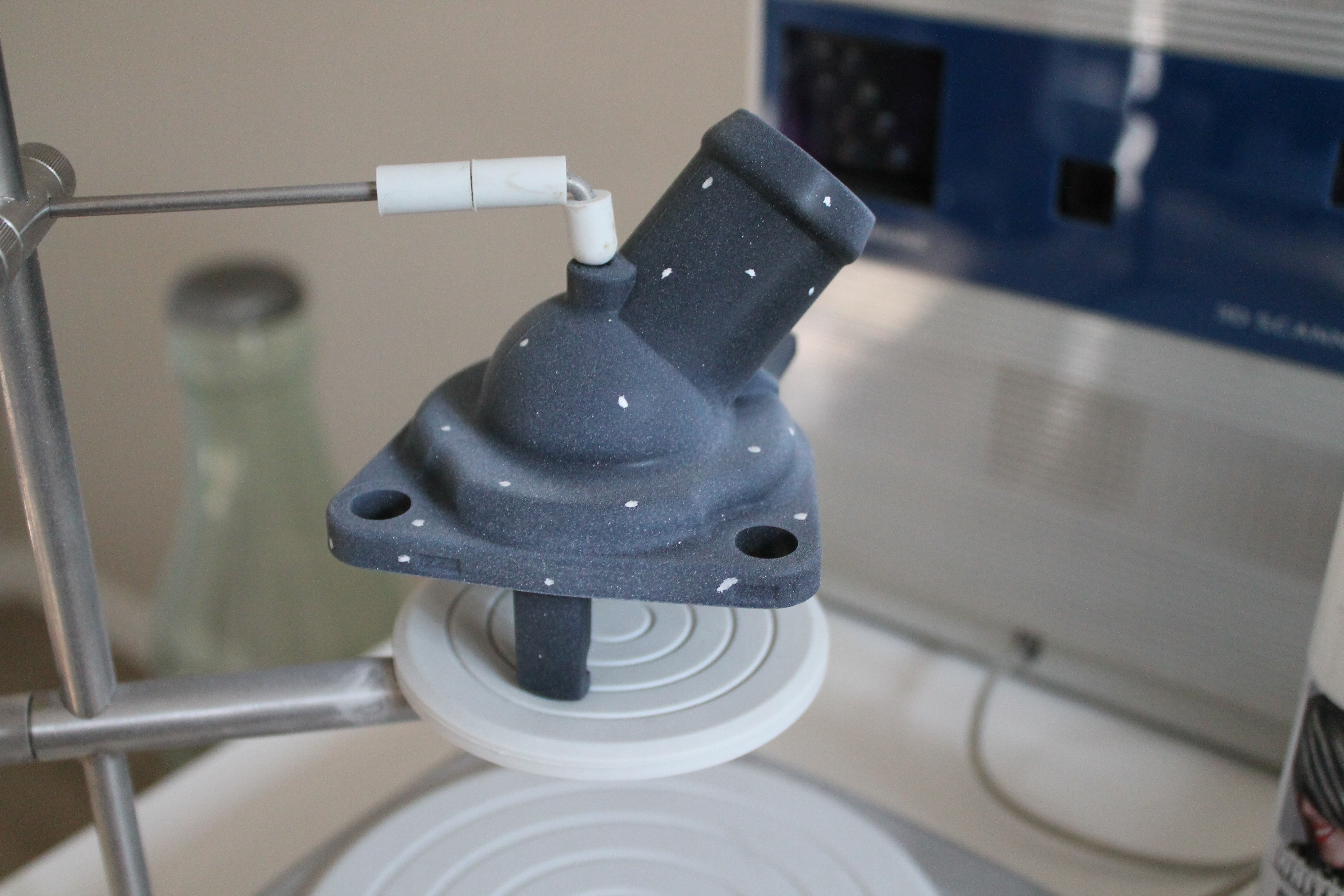
Surface Prep – To prevent lasers from reflecting or passing through the object which can cause distorted and missing data a matted white spray was applied to the surface using white hairspray. Other recommended coatings are flat white spray paint or foot powders.
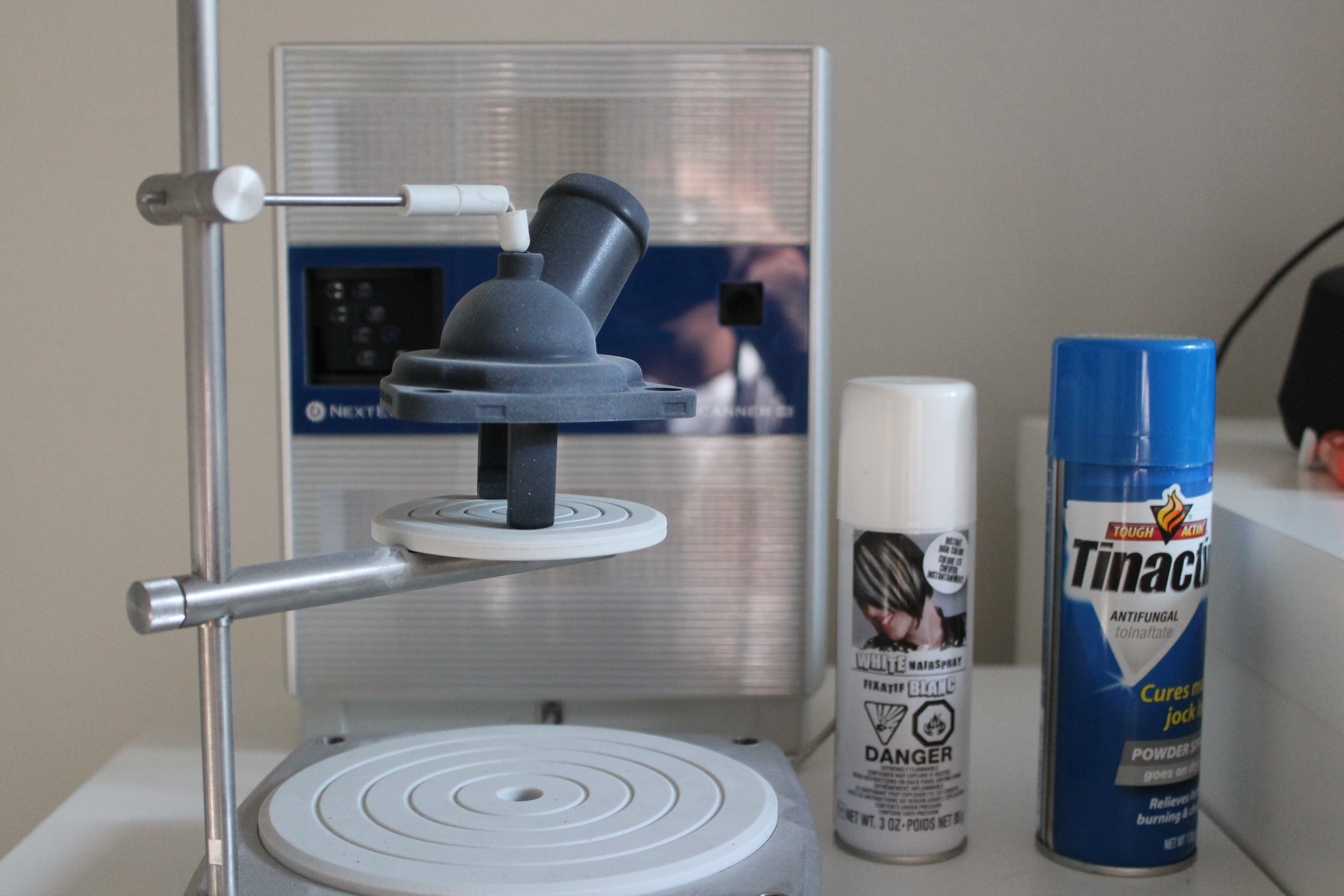
STEP 2: SCAN SETUP
Alignment Prep Marks– These marks will make it easier to identify locations on the object which will help align scans families.
Tip* – Staying in Focus – Position the scan object in focal range. This helps optimize scan quality and accuracy.
STEP 3: SCAN STUDIO CONTROL SETTINGS
A. Positioning – Determine how many view angles is needed for desired scan data.
360 – For every angle (ex: make a duplicate whole part)
Bracket – Three View Angles (ex: duplicate certain area of part)
Single – One View Angle (ex: duplicate only one view that is facing the scanner)
B. Divisions: Minimum of 7 Divisions -This is based on how many division is needed to capture data base on object complexity.
C. Speed: Set Speed to “SD” (Standard) – This setting should suffice with most scans.
D. Target: Depending on the object surface appearance, set to mode to either Dark, Neutral, or Light. In this example we have matte surface.
E. Range – This setting is the operating range and field of view. The setting should be base off the desired area of scan data required.
Macro – Field of View = ~5” x 3.75” at a distance 6.5”
Wide – Field of View = ~13.5” x 10” at a distance 17”
Note* Larger parts beyond the field of view can also be scan but may have to be scanned in smaller portions then grouped togethe

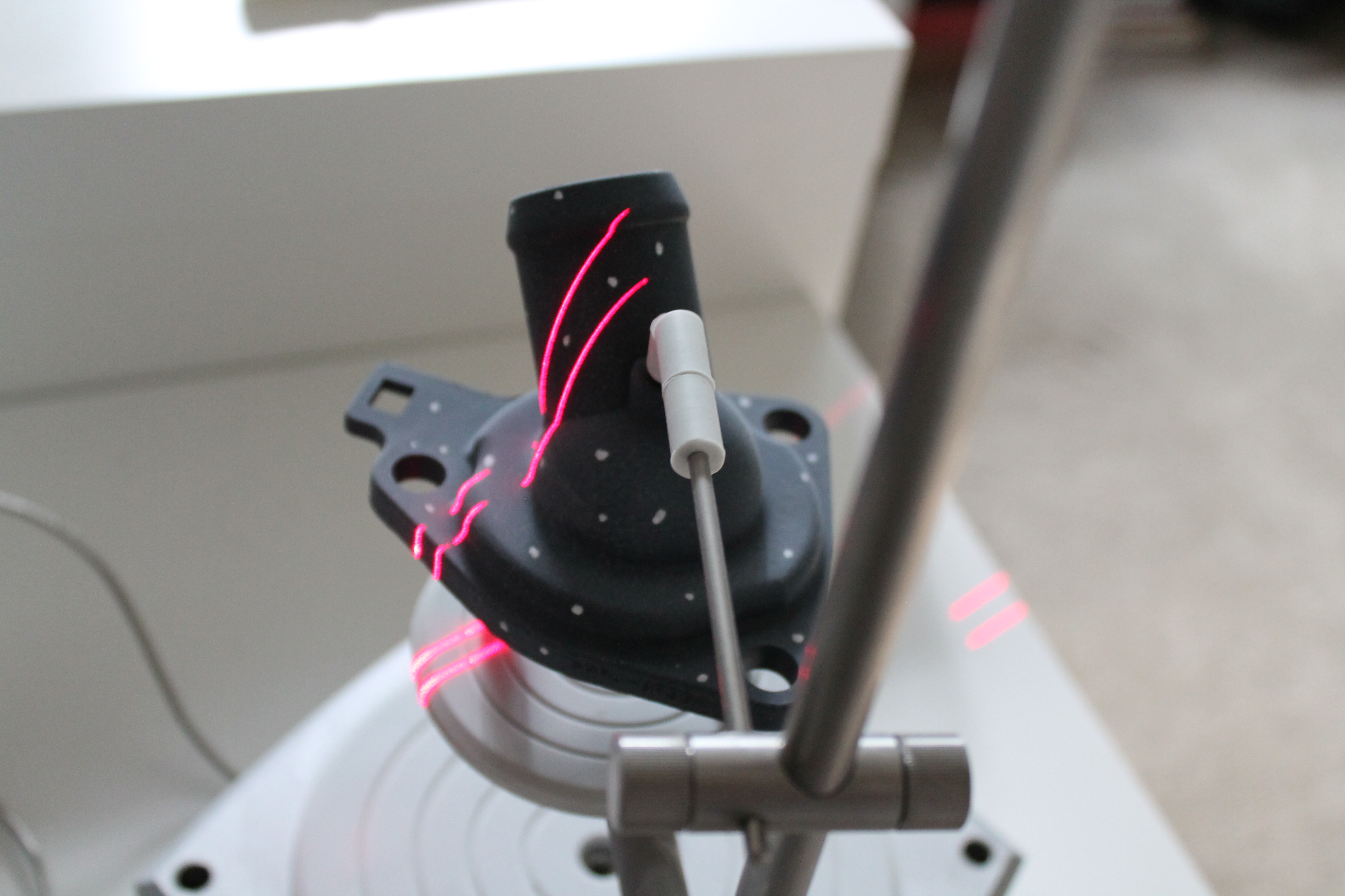
STEP 4: BEGIN SCAN
You are now ready to scan the object. The laser passing over the surface of the object is taking millions of data points. As each viewing angle is being captured you will notice that each scan is automatically aligning itself to next as your 3D scan model unfolds
STEP 5: ROTATE OBJECT UNTIL ALL FAMILY SCANS ARE CAPTURE
Repeat steps as needed to capture all areas of importance. Doing so we will be able to patch each family scan to merge into one. This is very important for large objects that are greater than the scanners working area.

STEP 6: MERGE AND REFINE 3D SCAN DATA
Raw laser scan data is them compiled and refine using features in Scan Studio or Rapidworks software. Features include: Trim, Align, Fuse, and Polish.


STEP 7: TURNING 3D SCAN DATA INTO A CAD MODEL
Next we will use the 3D Scan Data and import into Rapidworks to make a more idealized model that we can used for downstream applications.
This steps involve:
MESHING EDITING

REGION SEGMENTATION

CAD MODEL

ACCURACY ANALYSIS MAP

STEP 7: TRANSFER DIRECTLY INTO SOLIDWORKS
This happens via live transfer which is when Rapidworks communicates with Solidworks to send over the entire design feature tree that rebuilds the solid inside of Solidworks. So what you end up with is solid model native in Solidworks format with the complete feature tree intact.
For more information on the NextEngine 3D Scanner check out there website here. Also a good read would be this case study on a fishing reel where I scanned and digitalized it.