
Unicraft Automotive – C Pillar Trim Replacement
CASE STUDY
Andrew, owner of Unicraft Automotive reached out to me for help in reverse engineering and product development. When Andrew and I first met I could clearly see he was frustrated and overwhelmed. It was now going to be his third attempt at working with a designer. The first designer did an OK job but quickly ghosted him when manufacturing design issues came up. The second designer overpromised & underperformed. It didn’t stop there… It had cost Andrew $40,000 in total with all these attempts, not to mention all the personal time and sales opportunity lost.
I wasn’t surprised at all. I see this all too well when a client chooses to work with designers/manufactures who are undervalued, lacks clarity on the problem, and are paid too little to solve a big problem.
I wanted to fix this… But more important earn Andrew’s trust by being looked at as a partner who would serve to produce results (value) than rather be considered an expense.
The Problem
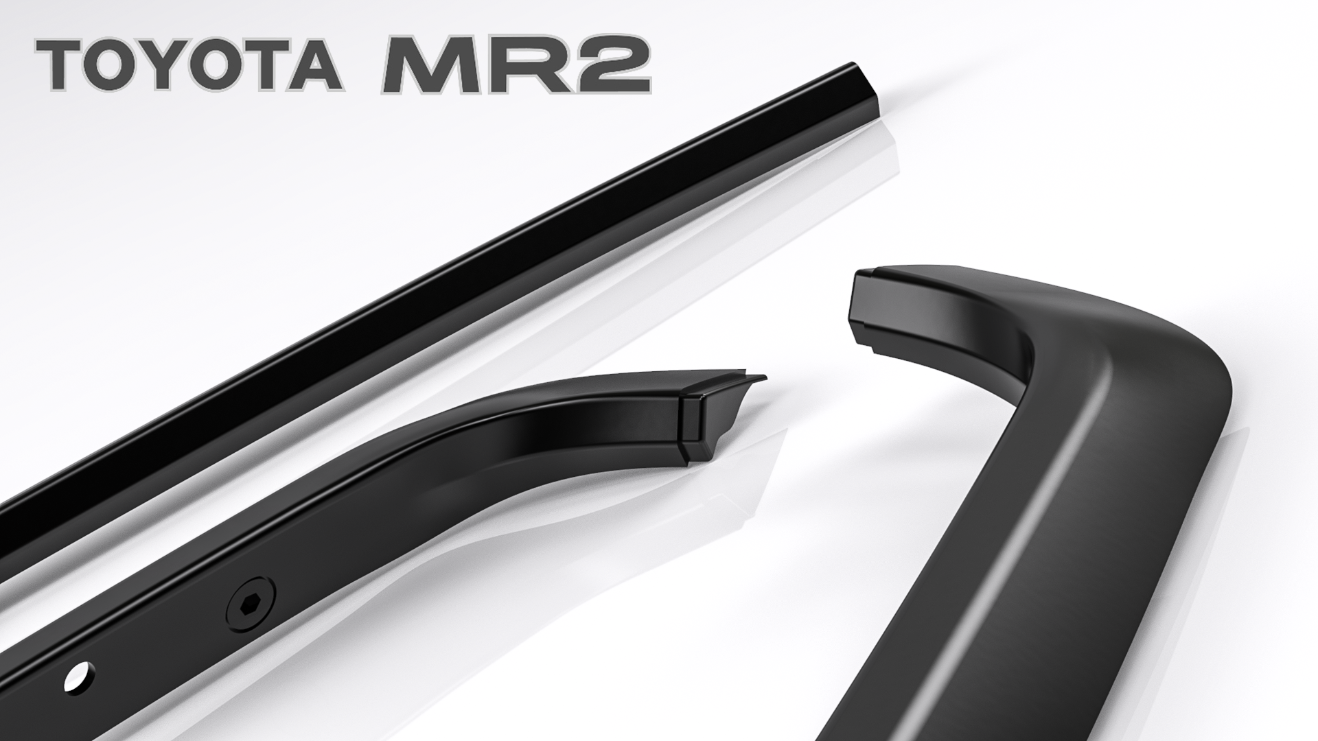
As older cars turn into collectables so do their counterparts. Andrew like many Toyota MR2 enthusiast face a common problem when trying to source replacement parts when restoring his vehicle. These parts happened to be the C-Pillar Trim Assembly. They normally are worn out, cracked, or severely damage. Since Toyota no longer makes them Andrew’s only option was to find a nicer used set either on Ebay or in the classified section of the forums. However, the issue was 1) scarcity, they were becoming super rare to find and if you did find a set 2) they cost over $800. This was becoming a problem and Andrew set out to make a replacement and he recruited me to help reverse engineer them.


The Solution
The original parts were plastic mold injected but the high tooling cost just didn’t make it a feasible route.
Therefore, Andrew decided early on that he wanted the MR2 C-Pillar trim pieces to be thermoformed. A manufacturing process where plastic sheet is heated then formed to a specific shape in a mold and later trimmed.


With some ingenuity, Andrew and I came up with a way where we could make a thermoformed process work. This involve taking the part thickness and making two halves. One sheet would be the top layer and the other the bottom. Then both layers get bonded to one another while having the custom fasteners sandwiched between the two. Then each hole and the outer edges would be cutout via CNC. The goal was to make it sure it met thermoformed design guidelines, was cost effective, and meet the functional/aesthetic requirements of the OE part.
3D Scanning
Next was to turn the trim pieces into digital models. To get accurate results, conventional measuring methods were not sufficient, instead the trim pieces needed to be 3D scanned and this 3D scan would be used as a basis for 3D modeling.
We chose to use the ATOS Blue Light 3D scanner over others on the market because it was able to capture complex shapes in high resolution while being able to pick up sharp edges from the trim pieces.


After the raw 3D scan data was captured it was brought into a reverse engineering software called Geomagic Design X to be refine further. This involves realign the scan data in a usable orientation and making sure the data was clean to work off of.


Converting Scan Data into a CAD Model
Traditionally when it comes to building CAD model from 3D scan data Geomagic Design X would suffice but because we would be making design changes, I decided to exported the 3D Scan data into an STL file to be open in SolidWorks where I would do most of the 3D modeling portion.
In SolidWorks I also prefer the sketching environment and surfacing tool features because the flexibility and control it had when creating complex surface geometry.

3D Model Plan in SolidWorks
- Best practices when working scan data in SW2018
- Create a Comparison Assembly
- Develop Modeling Strategy
- Constantly evaluate surface geometry and accuracy.
I found the best way to open and work with a 3d Scan STL in SolidWorks is to go into the open menu and from the dropdown menu select “Mesh(*.stl*,…,….)”. Then scroll over to options and import as “graphic body”. Select the .STL file then after the file has loaded it would be saved as a separate part file and name it “Partname_Scan”. I’ll explain why later.
Next is to confirm units and part alignment. In this case the center trim would benefit most as we would model one half then mirror. Before doing so, a critical step was to verify the scan data was symmetrical at the native right plane.


A rule I have is to never build the part in the same scanned part. Most scan .stl files can be very large (~ 500 MB) and we all know a file that size can get laggy and increase rebuild times. Instead of modeling the part in the same file as the STL file, I create a comparison assembly where I have both STL file and new SolidWorks model). This allows for shorter rebuild times and for easy showing/hiding of the STL reference.


Before I jumped into modeling, I need to develop a modeling strategy. This will help save time if changes are need down the modeling process.
For the C-Pillar Trim:
- Surface Patch Layout (4 -sides)
- Diving/Fading Surface Blends & Transitions
- Style Spline for Curvature Control
- Evaluate Surface Connections with Zebra Stripes
- Evaluate Surface Connections with Curvature Display
- Geometry Check
- Surface offset and Thicken
- Evaluate Manufacturing


For the Center Trim:
- Create one half then mirror
- Project Curves for surface sweep path
- Create Surface Plane at intersection of the surface and STL.
- Curvature and Zebra Stripe Analysis
- Overbuild approach them trim back
- Style splines for more curvature control
- Surface offset and Thicken
- Evaluate Manufacturing


Throughout the modeling process I’m always constantly checking for part accuracy. A hybrid approach is used by exporting the file as a Parasolid (*.x_t). Then import into Geomagic Design X where it becomes a solid Body. A deviation analysis performed where it takes the 3D scan data and overlaps it with the imported solid body. Once processed this display a color map of the discrepancy between the both scan data and solid body. Not only am I comparing accuracy but this helps me to match the 3D model to an agreed tolerance of .030″ or less. After some final adjustments the 3D model file is ready to be sent off to be 3D printed.


3D Printed Prototypes
Anytime tooling is involved in the production stage its always recommend a prototype be made as retooling cost can be quite expensive. Having prototypes will allow us to identify any fitment issues early in the development process and ensure that the part will fit before production begins.
We chose to go with an SLA high-resolution 3D print over using a cheaper hobbyist printer. The advantages were that SLA technology can handle larger print sizes, higher part accuracy, and produce a high-quality finish that was aesthetically pleasing. This also made it the right option as the material used was ABS-like which best match the OE part.


Fitment Check
Now came the moment of truth and I have to say I was somewhat nervous when it came to installing the 3D printed prototypes. But after the center trim went on my mind was at ease. It looked and fit perfect just like the OE part. We found no interference or alignment issues. Next was the C-pillar side trim. It fit like a glove. All holes lined up and the the spacing between the center trip was spot on.
After seeing the results, this verified that the reverse engineering and that the 3D CAD model was 100% correct. Andrew gave me the green light and I sent him the master files along with the BOM drawing for manufacturing to get started on tooling.


Tooling
Throughout the whole design process careful design for manufacturing was considered. This would insure that the part could be manufactured without any issues while maintaining design intent.


First Article Sample
After tooling was complete we received the first article samples (first test run of samples off tooling). From the samples we able to inspect the parts and verify fitment. Common issues that could be found were surface defects, tolerance issues, and bonding issues. We found none and confirmed with the factory to proceed with producing the first production batch of 100 in black.


Production Sample
First article samples have been approved. Unicraft has put in a the first order of 100 sets to be made from the factory and looking to have this available on the market for Toyota MR2 car enthusiasts by end of October 2019 just in time before Black Friday.
Conclusion
Coming soon…
[TEST_B id=4056]
Ready to get started?
Credits
Other Projects
-
 Zi Outdoors - Ruger 10/22 Scope MountZi Outdoors - Ruger 10/22 Scope Mount
 -
 Unicraft Automotive - C Pillar TrimUnicraft Automotive - C Pillar Trim
 -
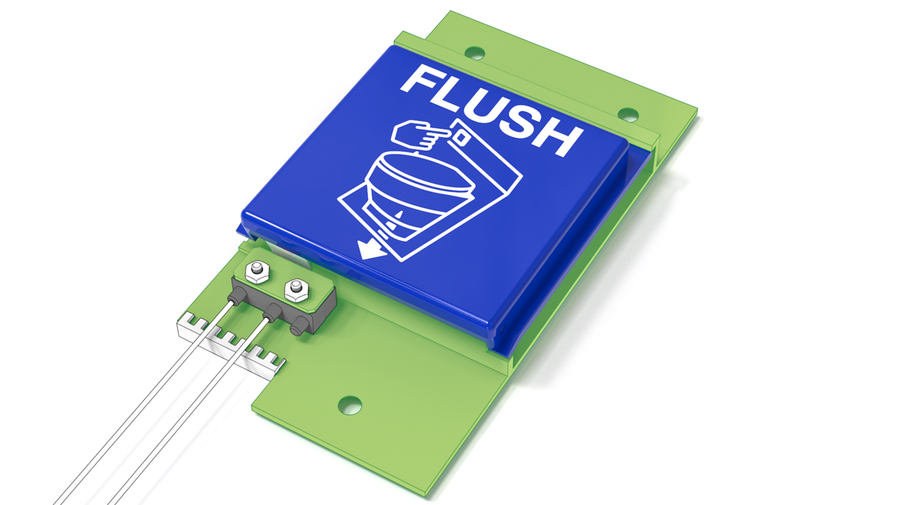 Soundair Aviation Services - Flush ButtonSoundair Aviation Services - Flush Button
 -
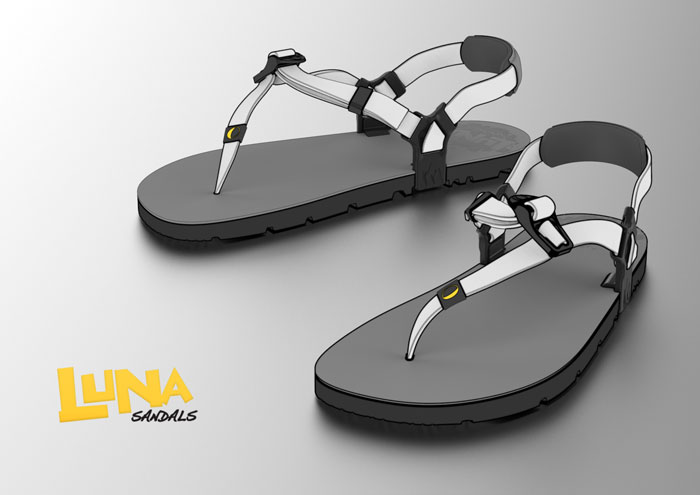 Luna Sandals - Wing PostLuna Sandals - Wing Post
 -
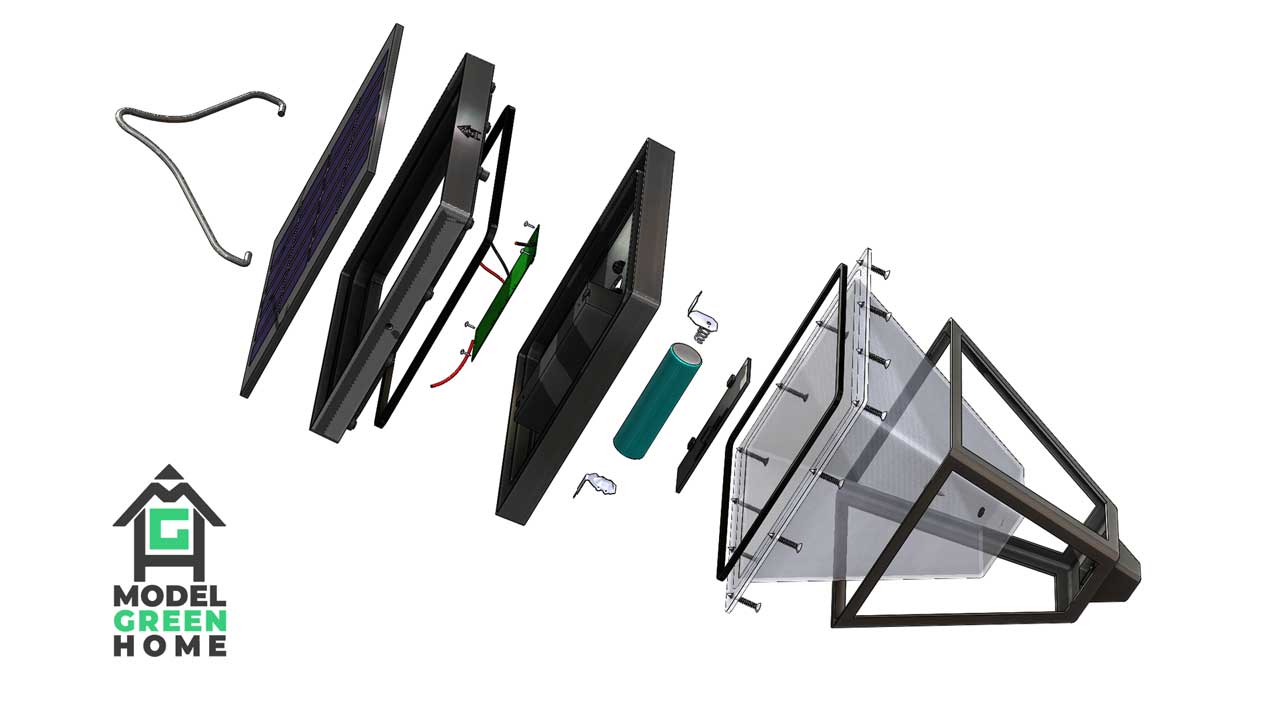 Model Green-Home - Solar Garden LightModel Green-Home - Solar Garden Light
 -
 LENSMATE - FUJI THUMBGRIPLENSMATE - FUJI THUMBGRIP
 -
 PERSONAL - ROD AND REEL REVERSE ENGINEERINGPERSONAL - ROD AND REEL REVERSE ENGINEERING
 -
 PERSONAL - 2D SKETCH TO 3D CAD MODELPERSONAL - 2D SKETCH TO 3D CAD MODEL
 -
 PeepShow - Bird HousePeepShow - Bird House